文献1(2017):铸造态钛合金力学性能及抗弹性能研究(Mechanical Properties and Ballistic Performance of As-cast Titanium
Alloys)
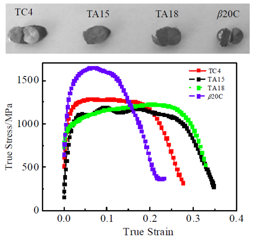
编号为TC4、TA15、TA18 和β20C 的动态压缩回收试样宏观照片如图3所示。由图3可知,在4000
s-1应变率条件下,试样沿着最大剪应力方向断裂失效,即与圆柱试样轴线成45°方向,该断裂类型属于典型的剪切断裂。动态真 (σ-ε)
曲线大致可分为弹性变形阶段和塑性流变阶段,以上两阶段各试样的曲线均未出现明显的屈服平台。试样发生屈服以后,随着试样塑性变形的增加,4
种试样的动态流变应力均无明显增加,说明这4种试样在高应变率条件下的应变强化效应都不明显。
![]()
图3 TC4、TA15、TA18、β20C 试样在应变率为4000 s-1下的变形与断裂与动态真应力-应变曲线
如图6所示,发现在7.62 mm穿甲弹以730 m·s-1的速度侵彻条件下,钛合金面板均被完全穿透。所有材料中,β20C的钛合金靶板正面开坑较大,尺寸为12
mm×10mm,弹坑内壁因出现崩落而造成孔壁凹凸不平,并且靶板未造成严重的冲塞破坏,同时背面没有出现翻唇现象,虽出现了背凸现象但并不明显,上述现象使得弹体在侵彻靶板的过程中消耗较多的能量,有利于靶板抗弹性能的提高。TC4、TA15及TA18钛合金正面开坑都没有β20C
明显,同时靶板背面都出现不同程度的背凸和翻唇现象,TA18 的翻唇现象表现得最为显著。TA15和TC4
靶板的孔壁光滑,为典型的绝热剪切冲塞破坏,当出现绝热剪切冲塞破坏现象时,装甲吸收弹丸的能量远低于其被塑性破坏时所吸收的能量,装甲对弹丸的阻力大大减小,绝热剪切冲塞的形成往往意味着靶材防护性能的彻底丧失。因此,TA15
钛合金靶板的残余穿深最大,其抗弹性能最差,β20C 钛合金靶板的残余穿深最小,其抗弹性能最好。
![]()
图6 钛合金靶板正面和背面的损伤情况
文献2(2015):Research of the Anti-Penetration Mechanism for Titanium Alloys Armor Based on 3D
Optical Scanning Technology(基于3D光学扫描技术的钛合金装甲抗侵彻机理研究)
Fig.4 shows the macroscopic appearance of the bullet hole on Ti-6Al-4V and β20C alloy target
plates obtained by 3D optical scanning. In Fig.4 (a) and (d), the front side of Ti-6Al-4V target
plate presents a larger reverse protrusion than that of β20C. Being restrained by 603 armor
steel plate, the backside of β20C target plate presents an obvious annular hump compared with
that of Ti-6Al-4V, as shown in Fig.4 (b) and (e). By comparing Fig.4 (c) with (f), it is
obviously noticed that there is a metal blocking in the bullet hole of Ti-6Al-4V plate, while
β20C plate has a continuous and open bullet hole. It is because the adiabatic shear makes the
temperature exceed the melting point of Ti-6Al-4V. Subsequently the solidified metal is jammed
in the bullet hole.
![]()
Fig.4. The macroscopic appearance of the bullet hole on titanium alloy target
(a)Front side of Ti-6Al-4V target (b) Backside of Ti-6Al-4V target (c) Section of bullet hole on
Ti-6Al-4V target (d) Front side of β20C target (e) Backside of β20C target (f) Section of the
bullet hole on β20C target
By 3D inverse operation, the 3D solid model of the bullet holes on Ti-6Al-4V and β20C target
plates were obtained, as shown in Fig.5 (a) and (b). The volumes and volume fractions of the
front crater region, the ductile hole-enlargement region, as well as the back caving region were
measured and summarized respectively in Table 3. It is necessary to state that the blocking part
of the ductile hole-enlargement region of Ti-6Al-4V (Fig.5 (a)) was included when calculating
the volume of the ductile hole-enlargement region. It can be clearly seen that the volume
fraction of the ductile hole-enlargement region is larger than the other regions of the bullet
hole for both Ti-6Al-4V and β20C. Further study shows that the volume fraction of the ductile
hole-enlargement of β20C, which is about 51%, is larger than that of Ti-6Al-4V, 41%. Moreover,
the volume fraction of the front crater region of β20C (about 15%) is less than that of
Ti-6Al-4V (about 26%). However, the volume fractions of the back caving region of these two
alloys are similar, approached to 33%.
![]()
Fig.5. The 3D solid shape of the bullet hole(a) Ti-6Al-4V (b) β20C

Research of the Anti-Penetration Mechanism for Titanium Alloys Armor Based on 3D Optical
Scanning Technology
Applied Mechanics and Materials 782(2015):164-169
[ PDF
Document Download
]
文献3(2015):Underlying mechanism of periodical adiabatic shear bands generated in Ti–6Al–4V target
by projectile impact(弹体撞击Ti-6Al-4V靶板产生周期性绝热剪切带的潜在机理)

The Penetration simulation results shows that the contour of the first principal stress in the
target plate at t=29μs, an exemplary time during the penetration process. Clearly, different
stress states are found in different regions of the target. The material near the free surfaces
of the target, such as in Cratering Zone I and Back Spalling Zone III, is in a state of tension
and the peak values are about 1400–1600 MPa. Conversely, in Ductile Hole Enlargement Zone II,
the material is under a compressive stress, and the maximum stress in this region reaches 1800
MPa.
![]()
Fig.5. The contour of the first principal stress in the target plate at t=29μs.
Zone I and Zone III are subjected to a circumferential tensile stress in a direction of normal to
the section plane of the target, and the material in these regions undergoes a small deformation
without directly interacting with the projectile. Such behavior reveals that the material in
these regions fails because of the stress accumulation. However, the material in Zone II suffers
from a circumferential and radial compressive stress and severe deformations, indicating that
the material in this location bears a high plastic deformation under a state of compression.
Thus, the plastic strain accumulates in those severely deformed elements, eventually reaching
the failure criteria. The accumulated plastic strain in this region could lead to an adiabatic
temperature rise, and, as the thermo-softening effect overcomes the rate of the strain hardening
effect, the ASBs are formed.
![]()
Fig.6. Vectors of the first principle stresses in three typical zones of the
target at t=29 μs.
Underlying mechanism of periodical adiabatic shear bands generated in Ti–6Al–4V target by
projectile impact
Materials and Design 87 (2015) 231–237
[ PDF
Document Download
]
文献4(2015):钛合金装甲材料动态压缩力学性能及其抗弹能力关系(Relationship between Dynamic Compressive Mechanical Properties
and Ballistic Performance of Titanium Armor Materials)
经3000 s-1 的应变率压缩后,获得编号为TC61、TC62、TC3、A4251、A4252 的5种Φ5 mm×5 mm
回收试样的宏观照片。由宏观照片可知,在3000 s-1
应变率条件下,试样断裂失效方向沿着最大剪应力方向,即与圆柱试样轴线成45°方向,属于典型的剪切断裂。从各试样动态真应力-真应变(σ-ε)曲线图可以看出,动态真应力-真应变(σ-ε)曲线大致可分为弹性阶段和塑性阶段,没有出现明显的屈服平台。在屈服以后,随着塑性变形的增加,5
种试样的动态流变应力均无明显增加,说明这5 种试样在高应变率条件下的应变强化效应不明显。
![]()
图3 编号为TC61、TC62、A4251、A4252、TC3 试样变形断裂宏观图及动态真应力-应变(σ-ε)曲线
分析钛合金面板的正面及背面宏观损伤形貌发现,在7.62 mm 穿甲弹以740 m/s 的速度侵彻条件下,钛合金面板均被完全穿透。所有材料中,TC61
的钛合金靶板正面开坑较大,尺寸约为13mm×10
mm,出现崩落造成孔壁凹凸不平,未造成严重的冲塞破坏,同时背面没有翻唇现象,背凸不明显,这些现象均使得弹体侵彻靶板的过程中消耗更多的能量,利于靶板抗弹性能的提高。相比较而言,其它编号的钛合金正面开坑都没有TC61
明显,同时靶板背面都出现不同程度的背凸和翻唇现象,TC3 的翻唇现象表现得最为显著。TC3
靶板的孔壁光滑,为典型的绝热剪切冲塞破坏,装甲出现冲塞破坏现象时,装甲吸收弹丸的能量远低于塑性破坏吸收的能量,对弹丸的阻力大大减小,冲塞的形成往往意味着靶材防护性能的彻底丧失。因此,TC3
钛合金靶板的防护系数最小,其抗弹性能最差。
![]()
图4 钛合金靶板正面和背面的损伤情况
文献5(2015):一种新型近 β 钛合金Ti684 动态力学性能与抗弹性能的研究(Dynamic Mechanical Properties and Ballistic
Performance of a Newly Developed Near-β Titanium Alloy Ti684)
图7为Ti-6Al-4V和900 ℃/15 min/WQ 处理后的Ti684试样靶板的损伤情况,实验所用靶板尺寸为Φ50mm×7.5mm,因尺寸较小,2
种靶板均碎裂,可以看出在弹坑位置处有一定程度的翻花现象。,Ti-6Al-4V试样靶板背板的残余穿深为11.9mm,质量防护系数为2.1,而900℃/15min/WQ处理后的Ti684
靶板背板的残余穿深为8.9 mm,质量防护系数为2.7,优于Ti-6Al-4V 靶板的抗弹性能。
![]()
图7 靶板经靶试试验后的损伤情况
图 9 为两种靶板弹坑断裂横截面的金相组织图,从图中可以看出900 ℃/15 min/WQ 处理后的Ti684 试样和Ti-6Al-4V 试样截面均出现绝热剪切, 但Ti-6Al-4V
靶板的绝热剪切带(图9a)呈现亮白色,数量大于 900 ℃/15 min/WQ 处理后的Ti684 靶板的灰色绝热剪切带(图9b)数量,同时Ti684
靶板的断裂面组织中出现了贯穿整个晶粒的不同位向的应变诱发马氏体。近来关于钛合金动态变形过程的研究表明,孪晶的产生会延迟绝热剪切带的产生,从而减小了绝热剪切带的形成;与此类似,应力诱发马氏体的产生大幅减小了绝热剪切带的数量,这主要是因为应力诱发马氏体相变过程中的滑移消耗了存储的动能,从而延迟了绝热剪切带的形成。
![]()
图9 靶板断口横截面的微观组织金相图
文献6(2014):Effects of dynamic mechanical properties on the ballistic performance of a new near-β
titanium alloy Ti684(动态力学性能对新型近β钛合金Ti684抗弹性能的影响)
Fig. 7 shows the damage observed for different target plates. It can be seen that the plates of
the Ti684 900℃ WQ sample (Fig. 7(a)) and Ti–6Al–4V (Fig. 7(d)) both break into three parts, the
760℃ STA sample (Fig. 7(b)) into four parts. The 800℃ STA sample (Fig. 7(c)) is the most
seriously damaged, breaking into seven parts. It is clear that the most seriously damaged 800℃
STA target has the deepest DOP of 12.52 mm, with a stand deviation 0.02 mm and shows the worst
ballistic performance. The 900℃ WQ sample has the minimum DOP of 8.86 mm, with a stand deviation
of 0.04 mm and shows the best ballistic performance. The 760℃ STA sample and Ti–6Al–4V have
similar residual depths.
![]()
Fig.7. Damage situation of titanium alloy target of all conditions. (a) 900℃ WQ,
(b) 760℃ STA, (c) 800℃ STA and (d) Ti–6Al–4V.
The SEM fractographs of the impact fracture surfaces of all samples are shown in Fig. 9. The 900℃
WQ sample (Fig. 9(a)), the 760℃ STA sample (Fig. 9(b)) and Ti–6Al–4V (Fig. 9(d)) all show
typical ductile fracture modes, with some ductile dimples, revealing that the target plates have
experienced obvious macroscopic plastic deformation before fracture, which can also be induced
from the critical fracture strain values illustrated in Fig. 6 and Table 4. In Fig. 9(c), the
800℃ STA samples exhibits brittle fracture, with little dimple fracture, indicating that the
fracture of the 800℃ STA sample is mainly of the brittle fracture type. The 900℃ WQ sample
impact fracture shows the largest region of dimples. Large amounts of energy are consumed during
the tearing process in ductile fracture, so under the highspeed impact of the armor piercing
projectiles, the ductile fracture process consumes more energy and the target plate with better
ductile fracture properties shows better ballistic impact performance.
![]()
Fig.9. Impact fracture surfaces (a) 900℃ WQ, (b) 760℃ STA, (c) 800℃ STA and (d)
Ti–6Al–4V.
Effects of dynamic mechanical properties on the ballistic performance of a new near-β
titanium alloy Ti684
Materials and Design 62 (2014) 233–240
[ PDF
Document Download
]
文献7(2012):Effects of Lamellar Microstructure Characteristics on Quasi-static and Dynamic
Deformation Behavior of Ti-6Al-4V-4Zr-Mo Alloys(层状组织特征对Ti-6Al-4V-4Zr-Mo合金准静态和动态变形行为的影响)
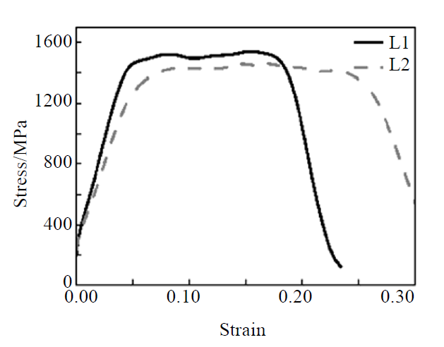
The true stress-strain curves of the Ti6441 alloys with different microstructure characteristics
are obtained from dynamic compression tests at the strain rate of 3000 s-1 (Fig.5).
It can be
seen from Fig.5 that the stress of the alloy with two different microstructures shows a similar
varied tendency, as the strain increases. The maximum stress point is reached immediately after
a little plastic deformation. After that, the flow stress roughly retains a certain value with
the increasing strain, due to the balance of strain, strain rate hardening and thermal softening
at the steady deformation stage. As the strain proceeds to increase, thermal softening, which
overrides strain rate hardening and strain hardening, is sufficient to induce plastic
instability and stress decreases sharply, resulting in the final adiabatic shear failure.
![]()
Fig.5 Stress-strain curves obtained from the dynamic compression tests
SEM fractographies of the Ti6441 alloys with different detailed characteristics of lamellar
microstructures are shown in Fig.6. As presented in Fig.6a, the fractured compressed specimens
for both the L1 and L2 lamellar microstructures show a typical adiabatic shear fracture mode,
composed of relatively smooth shear regions and ductile dimples, but dimples are elongated in
the shear direction compared with those of quasi-static tensile fractured specimens. It can be
induced from the SEM image that the L2 microstructure show higher dynamic ductility than the L1,
due to the following reasons: (1) voids (Fig.6b) are observed within the shear region of the L2
microstructure, explaining an additional consumption of energy; (2) dimples in larger value of
size are presented within the L2 microstructure, as shown in Fig.6c and 6d.
![]()
Fig.6 SEM fractographs of the dynamically fractured specimens for both the L1 and
L2 lamellar microstructures: (a) the same macro-fracture, (b) the local magnified micrograph of
smooth shear region of L2; and the dimples within L1 (c) and L2 (d)
Effects of Lamellar Microstructure Characteristics on Quasi-static and Dynamic Deformation
Behavior of Ti-6Al-4V-4Zr-Mo Alloys
Rare Metal Materials and Engineering 42(2013)57-461
[ PDF
Document Download
]