首页 >> 最新研究动态 >> 基于高通量扩散偶技术的Fe元素添加对双相钛合金组织及硬度的影响规律研究
基于高通量扩散偶技术的Fe元素添加对Ti-4.5Mo-5Al-1.8Zr-2.5Cr-1.1Sn钛合金组织及硬度的影响规律研究
发布时间:2022-05-18 发布人:材仿空间 研究文献发布相关信息
论文题目:Effect of Fe content on microstructure and hardness of Ti-4.5Mo–5Al-1.8Zr-2.5Cr-1.1Sn titanium alloy based on high-throughput diffusion couple
发表时间:Available online 4 April 2022
发表期刊: Materials Science & Engineering A [ 点击下载PDF ]

研究文献内容展示
Fig. 2(a) and Fig. 2(b) show microstructures of T20C-xFe highthroughput diffusion couple under SEM and distribution curves of chemical composition along two typical Fe atoms’ diffusion paths. These results are selected from several parallel experiments and can reflect the composition variations of diffusion couple. It can be seen from these two figures that the composition distribution on the two paths are similar after diffusion annealing. Due to interdiffusion between pure iron and T20C alloy, a high Fe content zone (HFZ) is formed near the side of pure iron, mostly in the range of 17–20 wt%. Noticeably, Fe content of local area in HFZ is up to 50 wt% (marked by red arrow in Fig. 2(b)), which may be caused by the precipitated phase.

Fig. 2. T20C-xFe high-throughput diffusion couple is observed under SEM. Starting from the points O1 and O2, which are separated by 0.5 mm in the Y direction, EDS point analysis was carried out along the diffusion direction(X direction) to obtain two curves in (a) and (b), respectively.
In order to further investigate the strengthening mechanism of thin short α laths in dual-phase microstructure of LFZ, thin film samples were obtained by FIB, just below two indentations with Fe contents of 2.73 wt % and 1.68 wt%, denoted as F1 and F2, respectively. The hardness at the two sites are 6.88 GPa and 6.13 GPa, respectively. Fig. 6(a) and Fig. 6(b) show the deformed microstructures near the indentation of F1 and F2 observed by TEM, respectively. It can be seen from Fig. 6(a) that due to the existence of many thin short α> laths in F1, the adjacent α laths may squeeze each other after a relatively short-distance slip or rotation process during compression deformation (marked by red arrows). Considering for the small area at a tip of α lath during deformation, it is easy to bear a high load and become a dislocation-rich region. Pile-up of dislocations at tips often leads to microstructure strengthening. Contrary to the situation of F1, according to Fig. 6(b), due to low quantity of thin short α laths in F2, there are few dislocation-rich regions at tips, resulting in weak dislocation strengthening during compression deformation.

Fig. 6. TEM images of deformation microstructures of regions below two indentations with Fe contents of (a) 2.73 wt% and (b) 1.68 wt%, respectively.
To describe the effect of Fe content on microstructure and hardness directly, a diagram of different microstructures with different Fe contents in LFZ under loading of an indenter is shown in Fig. 7. According to the difference of Fe contents, regions can be divided into high-Fe zone(>3.0 wt%), medium-Fe zone(2.5–3.0 wt%) and low-Fe zone(<2.5 wt%). In high-Fe zone, both the volume fraction and the number of dislocation-rich zones of α laths are lower than that in medium-Fe zone, resulting the effect of dislocation strengthening at tips of α laths and interface strengthening during compression deformation is weaker in this zone than that in medium-Fe zone, and thus resulting in lower hardness of this region than that of medium-Fe zone. Similarly, due to relatively lower volume fraction of thin short α laths in Low-Fe region, the effect of dislocation strengthening in Low-Fe zone is not as good as that of Medium-Fe zone, Therefore, the hardness of regions with Fe content in the range of 2.5–3.0 wt% on T20C-xFe high-throughput diffusion couple tends to reach the peak value.
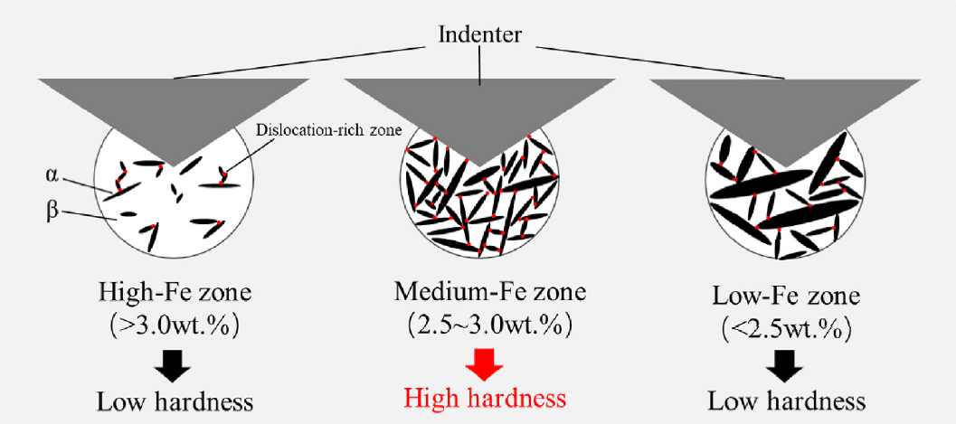
Fig. 7. The diagram of different microstructures with different Fe contents in LFZ under loading of an indenter.

京公网安备 11010802033099号
京ICP备2020038205号-1
